CVPV Module
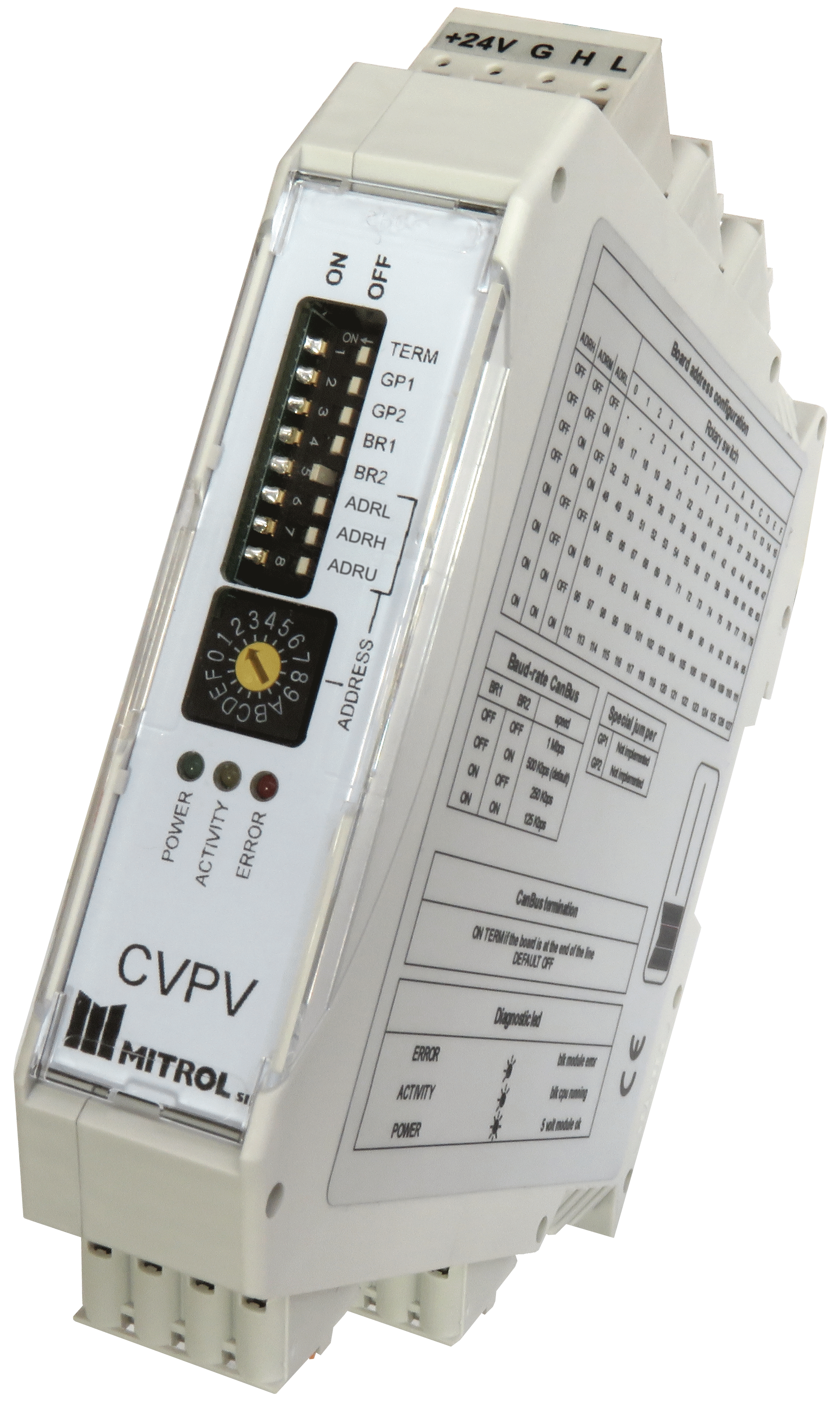
CVPV is a CanOpen protocol CanBus module, to be mounted on a standard DIN rail, for direct driving of hydraulic valves with solenoid current control.
The space required for installation is minimized by the vertical design of the module.
The module can drive 1 or 2 solenoids, depending on the type of valve: pressure or flow rate. Two different modules are available depending on the feedback signal source being internal or external. In both cases the reference signal is provided via CanBus.
In case of internal feedback the reference signal is a current signal, and the feedback loop closes on the output current measured inside the module.
In case of external loop the reference signal is of varying typology, and it must have the same physical dimensions of the feedback signal, measured on the second analog input. The feedback loop typology can be:
-
pressure loop with external pressure transducer;
-
flow rate loop if an external flow rate transducer is available;
-
position loop of an hydraulic cylinder using an external analogic position transducer mounted on a stand.
Calibration, and parameterization are performed via CanBus. It is possible to calibrate loop parameters, and the following additional settings are available:
-
5 point input characteristic linearization with deadband, and threshold handling.
-
Ramp to set the time to bring the reference from 0 to maximum.
-
Dither to be overlayed to the output current signal and whose frequency, and amplitude can be set.
Analog inputs can be connected from differential voltage inputs with dynamics 0/10 V or +10/-10 V, current signals with dynamics 4/20 mA or 0/20 mA, and potentiometric tranducers powered by the module.
4 groups of spring-cage connectors are provided:
-
One 4 points group, of which only 2 are used for 24 V power supply, and the other 2 are unused. The source this power supply is taken from is the same source the power supply for both for the module, and the solenoids, is taken;
-
Two 4 points group with the following purpose:
-
Potentiometer power supply positive pole;
-
Differential voltage signal input negative pole / Current input negative pole;
-
Differential voltage signal input positive pole / Current input positive pole / Potentiometric cursor;
-
Potentiometer power supply negative pole;
-
-
One 4 points connector, two for the positive solenoid, and two for the negative solenoid;
-
One 8 points group for the CanBus line, connected in pairs with the following scheme:
-
-
left (+24V_CAN)
-
middle left (GND_CAN)
-
middle right (CANH)
-
right (CANL)
-
Technical specifications
| Dimensions (H x W x D) | 120 x 22,5 x 114 mm |
| Mounting | Standard DIN rail |
| Power supply | 24 V (18 – 36 V) |
| Module logic power consumption | 100 mA |
| Analog input channels | 2 |
| Differential input voltage | 0/10 V o -10/10 V |
| Input current | 4/20 mA |
| Minimum potentiometer resistance | 1 KOhm |
| Potentiometer voltage reference | 10 V |
| ADC converter resolution | 12 bit |
| Power outputs | 1, for a bi solenoid valve |
| Nominal power output current | 2,5 A |
| Power output protection | Shortcircuit |
| Set-point linearization | Up to 5 points |
| PWM frequency | 1 kHz |
| Dither frequency | From 50Hz to 150 Hz |
| Dither amplitude | Up to 50% |
| CanBus Baud Rate | 125 kbps / 250 kbps / 500 kbps / 1 Mbps |
| Marking | CE |
| Operating Temperature | 0 ÷ 55°C |
| Warehousing Temperature | -20 ÷ 85 °C |
| Storage Humidity | Max 95% non-condensing |
| CanOpen Specification | DS301 |
Downloads
-
 Product leaflet
185.75 KB